History of Flexible Printed Circuit (FPC)
Do you know? Before Flexible Printed Circuit (FPC) became popular, Flat Flexible Cables (FFC) was the most used in the world. Let’s talk about the history of flexible circuit (FPC) in this PCB blog.
Elco and FFC History
Elco is the German subsidiary of an international company. In the 1970’s, flat flexible cables were adopted as a standard interface to jumper between printed circuit boards. While these cables provided design engineers significant packaging flexibility, the termination technology was limited to only two methods:
- Direct Solder: permanent connection for low cost applications.
- Crimped Contacts: separable connection for high end pluggability.
Seeing the demand for a cost-effective termination solution, Elco developed the first card edge style connector in 1986 which would mate directly to the FFC. This Low Insertion Force (LIF) type connector provided simple and reliable mating and unmating of the cable to the printed circuit board (PCB). Elco’s 8370 Series quickly became an industry standard for cost-effective FFC terminations. In 1987, Elco introduced the first Zero Insertion Force (ZIF) connector, Series 6200, which provided increased mating and unmating durability cycles.
Check to know more: Flexible Circuit with ZIF Connectors -Design, Manufacturing and Assembly
Since that time, Elco has continued to lead the industry with state-of-the-art products. Today Elco offers over 45 different product series for flexible circuits ranging between 1.25mm and 0.3mm pitch.
FFC Composition
Flat flexible cable (FFC) is made up of thin rectangular copper conductors laminated between two layers of polymer insulation. These copper conductors are left uncovered on each end and hen tin plated to make electrical contact with connector. A stiffener is bonded to the cable end which provides mechanical stability for the exposed copper conductors during mating and unmating. This type of cable is used when a straight one-to-one connection is required.
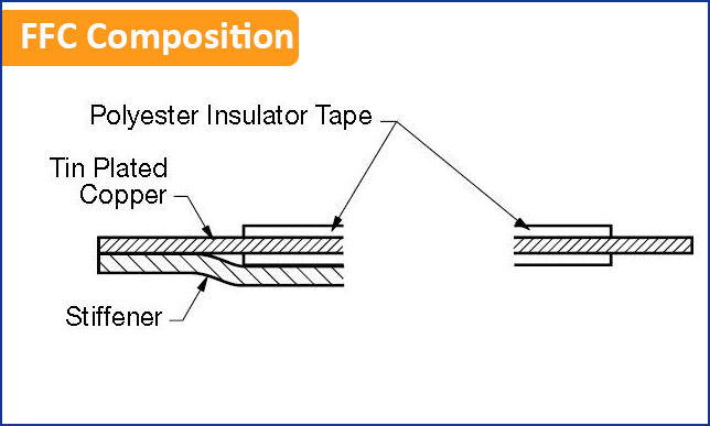
FPC Composition
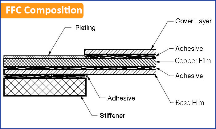
Flexible Printed Circuits (FPC) are similar in construction to the FFC except that copper film is chemically etched to produce a specific pattern. While these circuits are custom made for each application, various shapes and geometrics can solve the toughest packaging problems.
Carbon Paste
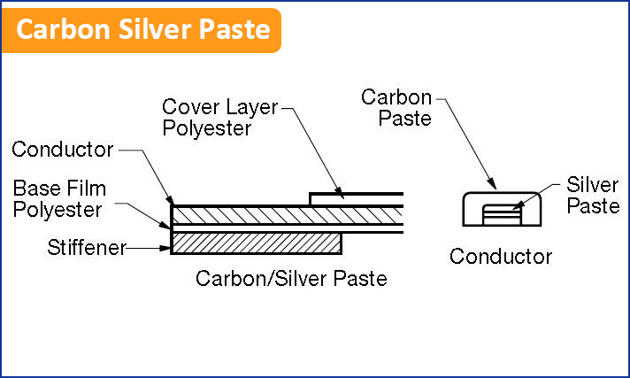
Screen printing with conductive carbon ink is the newest form of FPC (called membrane) being produced today. In this application, carbon/silver (C/Ag) paste replaces the traditional copper conductor. While very soft and easily damaged, these membrane circuits are cost effective to product and are lightweight.
Contact Design
In keeping pace with FFC/FPC technology, Elco has developed two different contact geometrics to guarantee reliable gas tight connections. The standard contact, which is available in all series was designed to mate all copper based FFC/FPC. This initial contact system proved to be too damaging to the softer carbon silver paste. In 1985, Elco introduced the first contact specifically designed for this application. Incorporating a radiused point, this new contact provides the reliability needed to meet today’s mechanical and environmental environments.
Connector Terminology
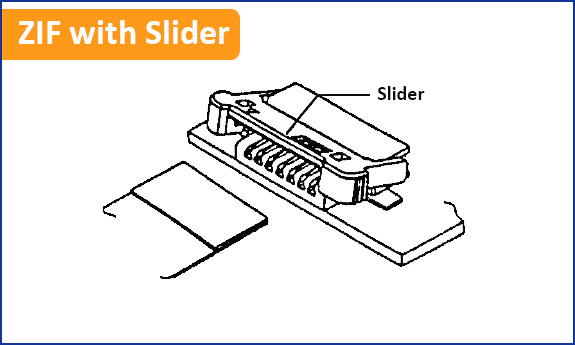
ZIF (Zero Insertion Force): ZIF connector style allows the highest possible number of mating cycles (30) for FFC/FPC. This connector incorporates a mechanical slider mechanism which snaps down over the cable after it is inserted into the insulator body.
LIF (Low Insertion Force): LIF connector style is the most cost-effective FFC/FPC connector while still providing reliability. The prepared cable is gently pressed into the insulator slot. There are no moving parts, however, maximum durability is 10 mating cycles.
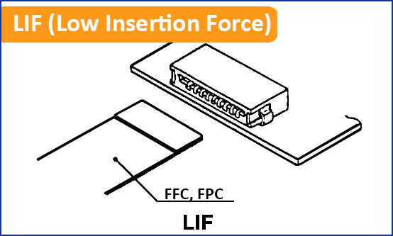
Functional Comparison of ZIF and LIF Connector
| — | Durability | Reliability | Cost | Size |
| ZIF | Better | Better | Good | Good |
| LIF | Good | Good | Better | Better |
PCB Termination Style
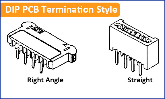
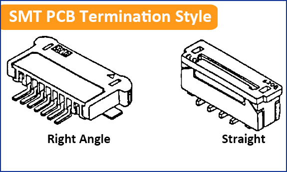
Placement Features
These help to position the connector on the printed circuit board and provide mechanical support, especially in SMT applications.
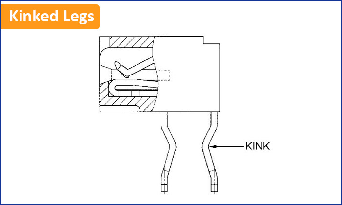
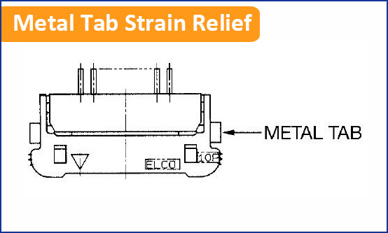
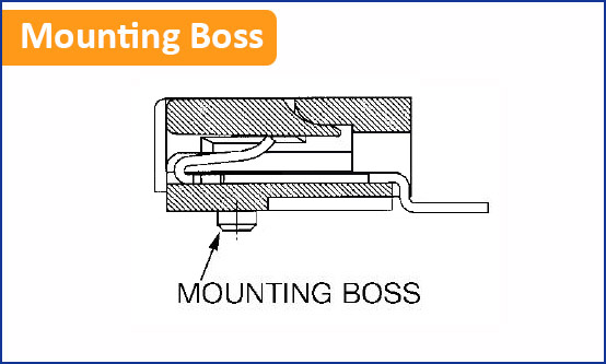
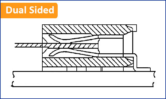
Contact Orientation
Dual Sided Contacts (LIF Only): Cable orientation is not as critical
Single Sided Contacts (Includes Top and Bottom): This style requires the FFC/FPC to be inserted into the insulator where by the exposed copper matches with the contact.
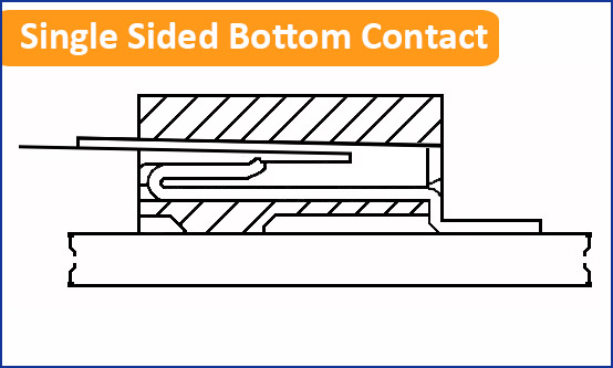
Choosing the correct connector eliminates flipping the FFC/FPC 180°. Examples:
Functional Comparison of Dual and Single Sided LIF Contacts
| — | Durability | Reliability | Cost | Orientation |
| Dual | Good | Better | Good | None |
| Single | Better | Good | Better | Yes |
Flexible Circuit & Assembly | Quick Quote
Are you finding a high-quality flexible circuit and assembly Manufacturer? We are one of the industry leading printed circuit board assembly suppliers, which provide quick turn PCB and assembly services around the world with PCB manufacturing, components sourcing, rigid-flex PCB assembly and testing. Some of our clients are in the fortune 500 companies. Get Quote today!
FR-4 PCB Quote Flexible PCB Quote Rigid-Flex PCB Quote IMS PCB Quote