PCB Panel, also referred as PCB array, is important for PCB manufacturing and assembly, and it helps to keep smaller PCB boards attached to one another in larger array. In this CAM dealing process, we call it as PCB Panelization. The purpose of PCB panel is to secure PCB boards during manufacturing, assembly, depanelization and shipping as painless as possible.
What is PCB Panelization?
A larger PCB panelized with several smaller individual PCBs is so called PCB Panelization. In mass production or quick turn PCB assembly orders, many PCB assembly manufacturers will use panelization to optimize output. The PCB fabricator will build blank PCB boards to use in the manufacturing process. The PCB designer will then find the best way to arrange the individual printed boards on a larger PCB no matter rigid PCBs or flexible PCBs.
PCB assembling on one large PCB panel has higher output than that of on several individual ones. The placement machines are able to secure the components to the boards as they move down the manufacturing line. But in low volume or prototype PCB orders, panelization may not be required.
PCB Panelization Methods
There are some methods to make panel in design and front-end CAM engineering stages, and some certain restrictions on panelization such as thickness and distance between individual circuit boards as well as the overall weight of the components. If a PCB board could be compromised due to lack of strength, the design will have to redone. As we know, V-cut (also named V-groove) and Routing are the 2 common panelization methods.
- V-cut Panelization
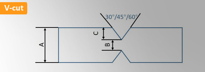
This is common method of panelization for separating individual PCBs with V-cut (also named V-grove). This removes approximately 1/3 of the PCB board’s thickness from the top and bottom of the printed circuit board with angled blade.

| V-cut / V-groove Capacities | |
| A: PCB thickness | 0.8-3.2mm |
| B: Remaining thickness | Standard: 1/3 of A, max: 0.8mm |
| C: V-grooved dimension | min: 0.25mm |
| Angle | 30°/45°/60° |
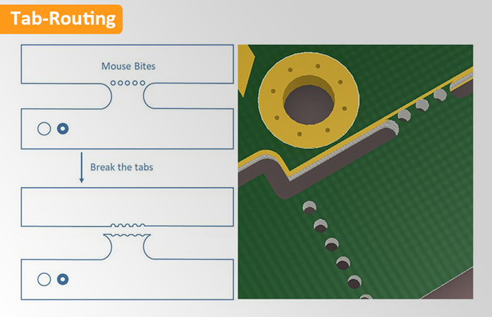
- Tab Routing Panelization with Mouse Bite Holes
PCB arrays that can’t feasibly use a V-cut method will instead use a tab routing method. With this method, PCBs are pre-cut from the array and held in place on the board with perforated tabs. 3 to 5 mouse bites holes are used in these perforation patterns. This method is often beneficial for its ability to support designs with edge-hanging components. It can also be broken by hand instead of with tools.
FR-4 PCB Quote Flexible PCB Quote Rigid-Flex PCB Quote IMS PCB Quote
