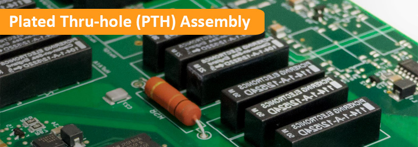
PTH stands for Plated Through-Holes, or Plated Thru-holes. PTH Assembly, also called as Through-hole Assembly, or Thru-hole Assembly, which is one of the PCB assembly technologies, means electronic components, especially DIP (Dual in-line Packages), inserted into the holes drilled and plated in the printed circuit board (PCB) and soldered to the pads on the opposite side either by manual assembly (hand placement) or by the use of automated insertion mount machines. The main advantage of PTH assembly is that electrical components can be mounted on both sides of the board, which saves space and money.
Through-hole PCB assembly technology almost completely replaced earlier electronics assembly techniques such as wire wrapping. From the 2nd generation of computers in the 1950s until surface-mount-technology (SMT) became popular late 1980s, every component on a typical PCB was a through-hole component. PCBs initially had tracks printed on one side only, later both sides, then multi-layer boards were in use. Through holes became plated-through-holes (PTH) in order for the components to make contact with the required conductive layers. Plated-through holes assembly no longer required with SMT boards for making the component connections, but are still used for making interconnections between the layers and in this role are more usually called vias. We are fully of providing prototype and small quantity, PTH PCB Assembly Services at the highest quality level possible in a cost-effective manner.
Through-hole mounting of components provides strong mechanical bonds when compared to the surface-mount technology, and gives extra space for the designer to route the tracks. However, surface mount components can allow for denser circuit configurations and utilize both sides of the board. Through-hole mounting is rebust connection.
Solderless Press-fit Component Assembly
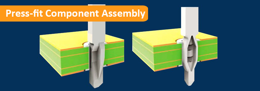
Press-fit holes are PTH with tighter tolerances than the standard +/-0.1mm. They are used as holes to fit the leads of connectors that will not be soldered but pressed into the holes. To accommodate lead and hole to tightly fit together, the tolerances on both are well defined and more tight than standard. Press-Fit can be optimized to provide a better-quality connection than blade-and-socket, practically eliminating the resistance and inductance that can impact circuit operation and reliability. It is also called solderless assembly.

Therefore, it is of utmost importance that these tolerances are well defined in your PCB date for the PCB Manufacturer, and that the parameter “Press Fit” is checked in the order details. If the Press-fit hole is too small, the PCB board will be damaged by press. And for Press-fit component assembly, it is not recommended to wave soldering because it can deconstruct the cold weld or delaminate the PCB. The pins of the Press-fit power elements are not made for soldering.
Our diligent staff ensures there is no compromise on quality since they are trained to follow all the inspection steps for low volume and prototype through-hole PCB assembly. We have a quality assurance team to monitor, inspect the processes and support continual process improvement. We currently employ numerous advanced test equipment including tests of AOI Testing, Visual inspection, X-ray Inspection, In-Circuit test, and optional Functional Testing to produce high-quality and cost-effective assembly.