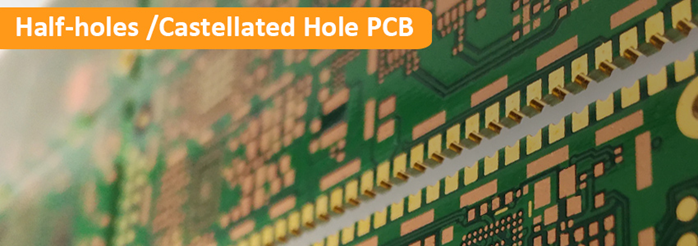
The higher level of plated edge is called plated Half-Holes PCB technology for printed circuit boards, also named as Castellated-Hole PCB, which rows of holes are routed alongside the boundaries of a PCB. Plated holes are routed in half on the boundary of the PCB so that the shape looks like the top of a plated, Half-Vias, Edge-Plating and Leadless Chip Carrier (LCC) PCB. Choosing a professional PCB provider and supplier, like Jichangsheng Technology, you will get high quality PCB delivery.
Half-holes PCB manufacturing Processes
Sounds like half-hole PCB fabrication is a simple process flow of drilling, plating and routing them in half, which is so simple. But in fact, it requires multiple additional processes and careful production planning during the CAM engineering preparation. The problem in these processes may happen is that the plated copper wall on the half holes break from the drill due to the horizontal routing force of the routing machine. As a consequence, all half-holes’ copper walls will be pressed into the holes from one side. For preventing from the copper walls from collapsing into the plated holes, we change the routing directions and add some processes. Some production processes are brought forward or done twice. Only such intensive preparation and adjustment if the half-holes PCB manufacturing process can assure that half-hole PCBs are produced with flawless castellated outline.
Key Consideration for Half-hole PCB Layout
It’s a key consideration for PCB layout that the minimum drill diameter for half-holes are 0.6mm. After halving them only 0.3mm are left. The minimum distance between the annular rings of the half-opens is 0.5mm. Furthermore, we recommend a chemical PCB surface finish such as ENIG (immersion gold) or ENEPIC (electroless nickel electroless palladium immersion gold). HAL (hot air levelling) may congest the hard-holes. Before sending PCB files to your provider and supplier, please check your PCB design carefully. Then the half-holes PCB manufacturer can do free DFM and proceed into fabrication quickly.
The following table contains the mininum parameters in plated half-holes PCB design and manufacturing.
| Min Drill Dia. | Min Pad Dia. | Min Pad/Pad Spacing |
| 0.6mm | 0.9mm | 0.25mm |
Function of Plated Half-holes PCBs
More and more often plated slots, plated edges or even completely plated outlines are required for PCB boards. While plated slots are relatively easy to produce. Plated Half-holes PCBs are predominantly used for board-to-board connections, mostly where two printed circuit boards with different technologies are combined. The half-holes PCBs can be standard PCBs and advanced PCBs. They may be included as a part of the board circuitry such accessing parts on a daughter board. The board-to-board PCBs need plated half-holes, which serve as SMD connection pads. Through directly connecting the PCBs together, the whole system is considerably thinner than a comparable connection with multi-pin connectors. The solder paste will climb onto the half holes when the half hole circuit board go through reflow soldering machine. The cooled solder paste on the half hole walls looks shining.
Applications of Half Holes PCBs
Plated half holes are economical connection techniques, which transform the board into a surface mount sub-assembly. They are frequently used as breakout circuits for find-pitch SMD components or on small radio or RF assemblies. Since they are plated and concave, these PCBs provide better landings for soldering. Their position on the boundaries of the board signifies that the surface mount components or daughter board will mount flush on the motherboard surface. There will be no space for dust or moisture to gather once the unit is place. Castellated holes PCBs (Half-holes PCBs) are widely applied for microcontroller modules, display, HF or ceramic modules which are soldered to the base PCBs.
How to Indicate Half Holes in Your PCB Design?
Half hole design varies from software to software, but the end result in Gerber files should be as follows. Add a via or plated hole directly on your outline of the PCB boards where the plated half hole is required. Ensure that half of the via is on the board and half is on the outside of the outline.
The following should be included:
- Copper layers (GTL and GBL): Copper pads on both top and bottom copper layers for each half hole.
- Solder mask layers (GTS and GBS): Solder mask openings on both sides.
- Drill layer (TXT/DRL): A drill hole for each half hole.
- Mechanical/Outline layer (GML/GKO): The outline should cross the drill hole.
Half Hole PCB Cost
As described in half hole PCB manufacturing processes, it requires more process and time consumption. Upon customer specifications, there is an additional cost for plated half holes PCB. The half hole PCB cost will be higher than that of standard PCB.