High Density Interconnect (HDI) PCBs are printed circuit boards with a much higher wiring and pad connection density than a conventional PCB. HDI PCBs are featured by fine trace and spacing, small pad, micro-via, blind and buried via, stager via, stack via, via-in-pad and via-on-pad. HDI PCB manufacturing is a fast-growing technology since market demand for thinner and smaller PCB boards, which can transmit high speed signals with low signal loss, have steadily increased.
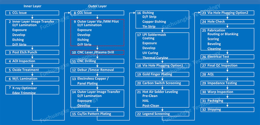
HDI PCB manufacturing process requires laser drilling, VCP plating, one or more sequential lamination cycles, high registration precision, non-conductive resin filling, copper filling, impedance control, and etc., which has higher requirements on manufacturing facilities, engineers and technicians. With the following HDI PCB Capabilities, our facilities have more comprehensive capabilities in PCB Fabrication and PCB Assembly. We are happy to provide Turnkey PCB Assembly services for HDI PCB prototype and mass production projects.
| Item | Standard | Advanced |
| Layer Count | 4-16 | 4-20 |
| Min Board Thickness | 0.35mm (13.78mil) | 0.3mm(11.8mil) |
| Max Board Thickness | 4.2mm (250mil) | 6mm (236mil) |
| Min Initial Copper Foil Weight | 1/3 oz | 1/3 oz |
| Min Mech Drill Diameter | 0.2mm (7.87mil) | 0.15mm (5.9mil) |
| Min Laser Drill Diameter | 0.1mm (4mil) | 0.1mm (4mil) |
| Min Finished Hole Size | 0.1mm (4mil) | 0.1mm (4mil) |
| Blind Via Finished Hole Size | 0.1mm (4mil) | 0 (Fully Plated shut) |
| Buried Via Finished Hole Size | 0.1mm (4mil) | 0.1mm (4mil) |
| Minimum Trace Width/Spacing | 3mil/3mil | 2.75mil/2.75mil |
| Min Pad Size for E-test | 6mil | 6mil |
| Minimum Wire Bond Pad size | > 6mil | 5mil |
| Controlled Impedance Tolerance | +/-5%, +/-10% | +/-5%, +/-10% |
| Solder Mask Registration | +/-2mil | +/-2mil |
| Solder Mask Min Dam Size | 0.1mm (4mil) | 0.1mm (4mil) |
| Min Diameter Rout Cutter Available | 0.6mm (24mil) | 0.6mm (24mil) |
| Laser Hole Location Tolerance | 0.5mil | 0.5mil |
| Thickness Tolerance | 10% (as per stack-up) | < 10% (as per stack-up) |
| Sequential Lamination | 3 or less lamination cycles | > 3 lamination cycles |
| Buried Vias | 2 or less | > 3 |
| Blind Vias | Yes | Yes |
| Stack Vias | Yes | Yes |
| Staggered Vias | Yes | Yes |
| Via-in-Pad | Yes | Yes |
| Conductive Filled Vias | Yes | Yes |
| Non-Conductive Filled Vias | Yes | Yes |
| Aspect Ratio | -10:1(HASL Lead free, HASL Lead, ENIG, Immersion Tin, Immersion silver, ENEPIG); -8:1(OSP) |
-10:1(HASL Lead free, HASL Lead, ENIG, Immersion Tin, Immersion silver, ENEPIG); -8:1(OSP) |
| Surface Finish | ||
| Flash Gold (Electroplated Gold) | Yes | Yes |
| ENIG | Yes | Yes |
| Hard Gold | Yes | Yes |
| Flash Gold | Yes | Yes |
| HASL Lead Free | Yes | Yes |
| ENEPIG | Yes | Yes |
| Soft Gold | Yes | Yes |
| Immersion Silver | Yes | Yes |
| Immersion Tin | Yes | Yes |
| ENIG+OSP | Yes | Yes |
| ENIG+Gold Finger | Yes | Yes |
| Flash Gold (Electroplated Gold)+Gold finger | Yes | Yes |
| Immersion Silver+Gold Finger | Yes | Yes |
| Immersion Tin+Gold finger | Yes | Yes |
| Solder Mask | ||
| Semi – Glossy | Yes | Yes |
| Glossy | Yes | Yes |
| Matte | Yes | Yes |
| Green | Yes | Yes |
| Black | Yes | Yes |
| Red | Yes | Yes |
| Blue | Yes | Yes |
| Yellow | Yes | Yes |
| White | Yes | Yes |
| Clear | Yes | Yes |
| Bright White | Yes | Yes |
| Purple | Yes | Yes |
| Silkscreen | ||
| All colors | Yes | Yes |
| Other Process | ||
| Routed Array | Yes | Yes |
| V-Cut, Edge to Copper | 0.25mm (9.8mil) | 0.25mm (9.8mil) |
| V-Cut Angle | 35°,45°,60° | 35°,45°,60° |
| Countersink | Yes | Yes |
| Counterbore | Yes | Yes |
| Beveling | Yes | Yes |
| Milling | +/-3mil | +/-3mil |
| Edge Castellation | Yes | Yes |
| Edge Plating | Yes | Yes |
| Heatsinks | Yes | Yes |
HDI PCB Sequential Build-Up (SBU) Technology
At present time, Fuchuangke Technology can provide sequential lamination PCB boards of up to 30 layers. Our PCB house has been equiped with advanced laser drilling machines, which are capable of laser drilling vias as small as 3mil (0.075mm). With SBU technology, we can provide inner and outer layers with as fine as 2.75/2.75mil trace width/space featuring excellent registration.
