HDI stands for High Density Interconnect. HDI PCBs represent one of the fastest growing segments of the printed circuit board market, which contributes to the high demand in the latest technologies available to increase the functionality of PCBs using the same or less amount of area. The technologies are driven by the components miniaturization and semiconductor packages that supports advanced features in revolutionary new products, including cameras, laptops, tablets, high-end earphones and game players, 4G and 5G network communications, AI and IoT (AIoT) technologies, and military applications. HDI boards are Multilayer PCBs, can be rigid FR4 PCBs, flexible circuits and rigid-flex PCBs. Fuchuangke Technology is a highly reliable HDI PCB supplier in China.
HDI printed circuit boards are with finer spaces and traces, minor vias and capture pads and higher connection pad density. It’s helpful in enhancing electrical performance and reduction in weight and size of the devices and products. HDI PCB technology is the better option for high-layer count and costly laminated boards.
We are an HDI PCB Manufacturer in Shenzhen. HDI PCB manufacturing has higher requirements on equipment, materials, engineers and workers than standard PCB. Our HDI capacities include laser micro-vias, blind and buried vias, fine lines and spaces, sequential lamination, via-in-pad (plated with copper and planarized flat) technology. We support HDI PCB prototype and mass production with less expensive price and quick-turn lead time. Customers from a variety of industries we serve have a common that have high expectations in quality, reliability and on-time delivery in HDI PCB production. Our quality is not afterthought, but built into each process from front-end to fabrication and shipping.
What’s HDI Microvia?

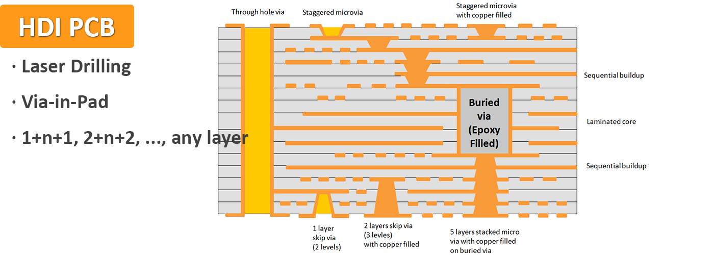
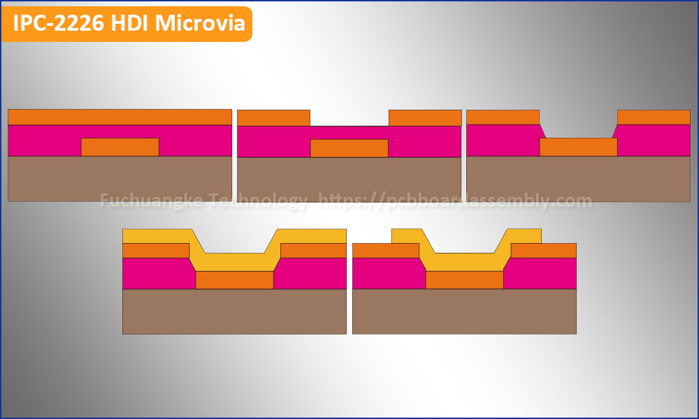
As newer devices require higher component densities, microvias are becoming more common in HDI PCB designs. Multilayer boards with smaller traces at high-density also require microvias to route your signals. Microvia is the very important role in HDI circuit board. But HDI PCB fabrication has strict requirement on microvia processing. A microvia maintains a laser drilled diameter of typically 6mil (0.15mm), 5mil (0.125mm), 4mil (0.1mm), which are optically aligned and require a pad diameter typically 12mil (0.3mm), 10mil (0.25mm), 8mil (0.2mm), allowing additional routing density. Microvias can be via-in-pad, offset, staggered or stacked, non-conductive filled and copper plated over the top or solid copper filled or plated.

How Many Types of HDI PCB Stack-ups?
- 1+N+1 with laser microvia and mechanical buried core via. The “1” represents “build-up” or sequential lamination on each side of the core.
- i+N+i (i>=2) – PCBs contain 2 or more “build-up” of high-density interconnect layers. Microvias on different layers can be staggered or stacked. Copper filled stacked microvia structures are commonly seen in challenging designs.
- Any Layer HDI (ELIC) – All the layers of a PCB are high-density interconnection layers which allows the conductors on any layer of the PCB to be interconnected freely with copper filled stacked microvia structures (“any layer via”). This provides a reliable interconnect solution for highly complex large pin-count devices, such as CPU and GPU chips utilized on handheld and mobile devices.
What Are the HDI Technologies Advantages?
By using HDI manufacturing technology, electronic hardware designers now have the option to place more components onto both sides of the bare HDI PCB. Multiple via processes, including via in pad and blind via technology, allow designers more PCB space to place components that are smaller even closer together. Decreased component package and pitch allow for more input and output in smaller areas. This means faster transmission of signals and a significant reduction in signal loss and crossing delays.
What’s Via-in-Pad Process?
Inspired from SMT technology, the limits with BGA’s, COB and CSP have been pushed into smaller PCB square surface. The via in pad process allows vias to be placed within the surface of the flat lands. The vias are plated and filled with conductive or non-conductive epoxy then capped and plated over, making them virtually invisible but interconnected between inner and outer layers. Via in pad process sounds simple, but need increase average eight additional manufacturing steps to complete this unique process, upon advanced equipment and skilled technicians follow the process carefully to achieve the perfect buried and/or blind vias.
What Are the Via Fill Types?
There are 4 types of via fill materials we have including non-conductive epoxy, conductive epoxy, copper filled, and electrochemical plating. All of them can make a via buried within a flat land, which is the same as the normal SMT land. Vias and microvias are drilled, blind or buried, filled then plated and hidden under SMT lands. Processing vias of this type requires special equipment and is much time consuming. The multiple drill cycles and controlled depth drilling adds to process time. Of course, the time consuming will increase HDI PCB price.
How is the Cost Performance of HDI PCB?
When some consumer products, like smart mobile main board, require light, thin and small, quality remains the most important factor for the consumers second to price. Using HDI technology during PCB design stage, it’s fully possible to reduce an 8 layers through-hole PCB to a 4 layers HDI PCB board with the micro-vias interconnection property. Both the wiring density and interconnection of a HDI board are better than a standard through-hole PCB. That’s to say, a well-designed 4 layers HDI PCB can achieve the same or better functions as that of a standard 8 layers PCB. But what’s the HDI PCB price? Of course, it’s higher than that of a standard PCB if with the same layer count, that’s because the microvia process increases the cost of the HDI PCB. But the proper HDI PCB design and reduction in layer count will reduce cost in material and layer count more significantly. Thus, the cost performance of HDI PCB is high in a certain sense.
Keys to Build HDI Boards
HDI PCB manufacturer and provider requires special equipment and processes such as laser machines for laser drilling, plugging, LDI (laser direct imaging) and sequential lamination cycles. HDI boards have thinner lines, tighter spacing and tighter annular ring, and use thinner specialty materials. In order to successfully produce HDI boards, it requires additional time and a significant investment in manufacturing processes and equipment.
- Non-contact Laser Drilling Technology
Unlike other conventional drills, the laser drilling process doesn’t physically contact the material that it is working with. Drilling the smallest of micro-vias allows for more technology on the board’s surface. The high influence beam of the laser machine can drill through metal and glass to create the tiny via hole. HDI PCBs always have a large laser drilling quantity per square meter, even more than 50K since its high-density interconnection, and the laser machine drilling capacity always reaches 4.3million per day.
- SBU (Sequential Build-up) Lamination
The use of a laser drill to produce holes in the internal layers allows for plating, imaging and etching prior to pressing. This added process is known as Sequential Build-up. SBU fabrication uses solid filled vias allowing for better thermal management, a stronger interconnect and increasing the board’s reliability.
- RCC – Resin Coated Copper
Resin coated copper was developed specifically to aide with poor hole quality, longer drill times and to allow for thinner PCBs. RCC has an ultra-low profile and ultra-thin copper foil that is anchored with minuscule nodules to the surface. This material is chemically treated and primed for the thinnest and finest line and spacing technology.
- LDI – Laser Drilling Imaging
Imaging finer lines than ever before to process these HDI parts is costly but necessary. Finer lines, spacing and annular ring requires much tighter controls. With use of finer lines, touch up rework or repair becomes an impossible task. Photo tool quality, laminate prepreg and imaging parameters are necessary for successful process. LDI (Laser Direct Imaging) is a far better option for such fine lines and spacing. Our HDI PCB production facilities use the latest technology equipment to produce this advanced PCB.
How to Get Low Cost HDI PCB?
There are many different factors affect the cost of an HDI board. Just keep these tips in mind to throughout your design stage, to determine your budget and ensure your PCB order is as cost-effective as possible.
- Type and Quantity of Vias, Thru-holes or Microvias
The via, micro-via or thru-holes you choose for your board will impact its cost, as will the quantity of these features you need. Smaller vias cost more than larger ones because they require more precision. Of course, adding more vias can also increase the price.
- HDI Structure and Layer Count
The HDI PCB structure you require will affect the cost, as well. A 2+N+2 layout is more complicated than a 1+N+1, so it will be more expensive. Additional layers will increase the price. You should aim for the most cost-effective and efficient layer count.
- Number of Sequential Laminations
The number of layers and the number of via structure types determine the number of sequential laminations required. Although more laminations mean more processing time and higher cost, adding more can make improved product performance and cost-effectiveness.
- Stacked vs. Staggered Vias
There can also be cost variations between stacked and staggered setups. Stacked vias can be filled with copper, but staggered micro-vias do not. Filling the vias means more processing, material and time is required to complete the project.

- Pad Size
You should aim to determine the size of the pad early on to help lower costs. Knowing the proper pad size will help you plan design efficiently and cost-effectively.