Laser Drilling Advantages in HDI PCB Manufacturing

Nowadays, electronic devices tend to require higher component and trace densities, vias are becoming progressively smaller with higher aspect ratios. Microvias are more in multilayer PCB boards with smaller traces down to 3mil (0.075mm). Microvias play a critical role in creating high density interconnects (HDI) for printed circuit boards (PCBs). Most PCB manufacturers can place via holes down to 6mil (0.15mm) in diameter, but the tooling costs actually increase with mechanical drilling. This is because the drills used are so thin that they snap very easily, especially if your microvias have high aspect ratio.
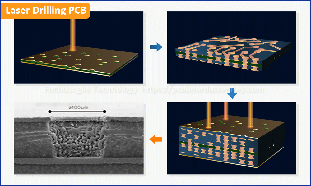
In traditional PCB manufacturing, it was a challenging to drill small holes smaller than 6mil (0.15mm). When the laser drilling technology got fast development. Laser drilling overcome a lot of limitations placed on traditional mechanical drilling, and can be used to make microvias in HDI Printed Circuit Board Fabrication, and is no limited by the same material constraints.
Smaller holes are possible, and laser drilling PCB became possible.
Main Advantages of Laser Drilling PCB are:
- Laser drilling is a non-conduct technique. The drilling medium is a beam of light, therefore there is no physical contact between (moving) parts and the workpiece printed circuit board. This prevents contamination of the PCB board and wear of the drilling part.
- Laser drilling can drill micro vias in diameter 3mil (0.075mm), 4mil (0.1mm), 5mil (0.127mm) and 6mil (0.15mm), which the traditional mechanical drilling cannot or hard to reach. This microvia laser drilling makes the high-density interconnect PCB routing technology possible, and contributes to the rapid development of HDI boards.
- High aspect ratios (depth to hole diameter) possible. In standard PCB manufacturing, most PCB manufacturer can only reach 8:1 or 10:1. When it is 8:1, if the PCB thickness is 62mil (1.6mm), the minimum drilling diameter is 8mil (0.2mm). When it is 10:1, the same PCB thickness, the minimum drilling diameter is 6mil (0.15mm). Only a few PCB producers can reach 6mil mechanical drilling, but the drilling efficiency is much lower and more expensive than laser drilling.
- High Speed. When the bare PCB has a large quantity of holes to drill, laser via drilling has faster drill speed compared to mechanical drilling. It can also be used to easily drill dense via holes in circuitry on a multilayer board. Over time, the tooling costs from mechanical drilling outweigh the benefits provided by laser drilling. Lasers with wavelengths ranging from deep infrared to ultraviolet can be used for laser drilling.
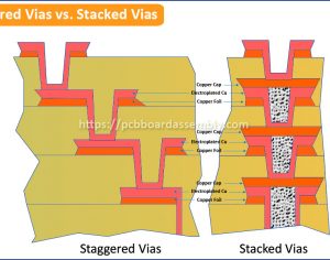
- High Precision. The PTH tolerance is +/-4mil and NPTH tolerance is +/-3mil in mechanical drilling. But laser via precision is reaching close to perfection. Laser drilling is suitable to form blind and buried vias, stacked vias in HDI board manufacturing.
- The focused laser beam is limited in the depth that can be reliably and reproducibly drilled. If a single lens is used to focus the beam, the laser is limited in the depth it can drill due to the limited depth of focus. As you may know, using a collimated laser beam would allow you to laser drill down to a greater depth. The problem with this is that the size of the via is so small that the beam experiences Fresnel diffraction, which can affect the intensity of the beam in very deep via holes. While, PCB manufacturers always drill those holes smaller than 6mil.
HDI PCB Quote
Fuchuangke Technology is professional HDI PCB Manufacturer in China, just submit your PCB design files to us for your HDI PCB fabrication. The HDI PCB board types can be FR4 rigid, flexible and rigid-flex with structure from 1+n+1 to ELIC (every layer interconnect). If also need turnkey PCB assembly service, just click any one of quick quote buttons below to fill in PCB specifications and upload your PCB files, the quote will be sent quickly.
FR-4 PCB Quote Flexible PCB Quote Rigid-Flex PCB Quote
