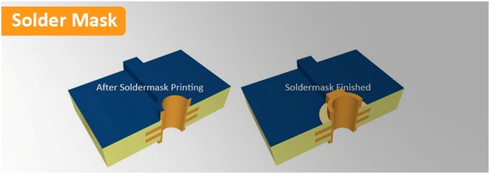
PCB Solder Mask, also written as Soldermask, which is a protective layer of liquid photo imageable lacquer applied on the TOP and BOTTOM side of a Printed Circuit Board. The function of the Soldermask is to protect the copper, apart from the solder pads, from:
- Oxidation
- Creating shorts during soldering (bridges)
- Creating shorts during operation due to external conductive influences
- Creating shorts during operation from net to net due to high voltage spikes
- Environmental influences like dust and other contaminations that may create shorts in the long run
The Soldermask is first printed or sprayed on to the production panel and then UV-exposed with the correct solder mask pattern, developed and dried. Solder mask is usually green but can also applied as black, white, blue, red, yellow, purple in natural and matt.
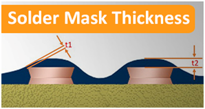
Soldermask Thickness

- On conductor side edges: >7 micron (t1)
- On conductor top: >7micron (t2)
- Maximum Soldermask Thickness can be up to 40?m for 35?m (1oz) finished copper thickness.
- For higher final copper thicknesses, the Soldermask Thickness can be up to 80?m
How to Print Solder Mask?
Most Circuit Boards have an epoxy-ink Soldermask printed onto each side to protect the copper surface and prevent solder shorting between components during PCB Assembly. The panels are first cleaned and brushed to remove any surface tarnish and then are conveyorized into the yellow room.
Each panel is given a final clean to remove any dust from the surface and loaded into the vertical coater. The coating machine simultaneously covers both sides of the panel with the epoxy Soldermask Ink. The double action ensures that the ink completely encapsulates the copper tracking, typically now 35-40 microns higher than the surface of the panel.
The panels are now racked and put through a conveyorized drier which hardens the resist just enough to allow it to be printed (“tack-dried”. The operator checks for a complete and even coating.
Next the coated panels are imaged. For this we use a two UV printer. The operator mounts the photo tool films on the machine and then places the panel onto the registration pins. The operator checks that the etching and plating resists used earlier in the process, the UV lamps in the machine harden the ink where the film is clear, that is where we need Soldermask on the finished Circuit Board.
The imaged panels are put on a conveyor out of the clean room and into the developer which strips off the unhardened and unwanted resist. Later the required resist will be further hardened or “cured” to provide a robust and permanent coat. For this we use a conveyorized oven in the same way in which the PCB Boards were previously tack-dried. But first the operator checks the alignment of the Soldermask on the panel and makes sure that are no traces of ink on the pads or through the holes. Even slight traces will compromise the Solderability of the finished PCB Boards.
What We Allow and What Not for Solder Mask Registration?
The Soldermask may encroach on lands as long as the minimum annular ring requirements are maintained. Soldermask is permitted in those PTH not intended for solder fill.
- No isolated pads are exposed.
- On SMT-pads with pitch 1.25mm encroachment is permitted on one side of land only and does not exceed 2mil (50micron).
- On SMT-pads with pitch <1.25mm encroachment is permitted on one side of land only and does not exceed 1mil (25micron).